

Description
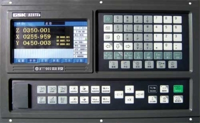
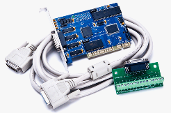
The LN8800 Controller CNC Machines.
Introduction of Basic Concepts
1. Introduction of Spatial Coordinates (position and stance)
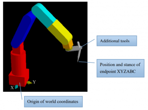
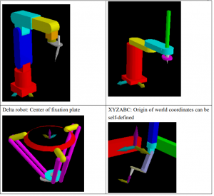
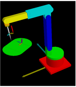
The coordinates of robot generally refer to the position and stance of endpoint, as shown in the figure below of a six-joint robot with additional tools. The origin joint (base coordinate system) of world coordinate system of Advantech LNC articulated robot is defined at the center of base, and the robot is regarded as a person in the definitions of directions of XYZ axes, where +X is on the right, +Y is at the front, and +Z is upward, just like the directions of commonly known coordinate system.
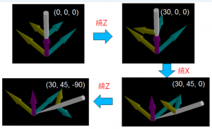
Both stance and position must be used for the expression of information of spatial coordinates. The position in any space can be shown as the frequently used (X, Y, Z), but the stance information (A, B, C) is not that easy to understand. A, B, and C are used for indicating the direction of endpoint based on a specific rule generally known as Euler’s rotation theorem, which can be used to indicate the possibilities of various directions. Please search online for a more detailed description of Euler’s rotation theorem. Each
robot system can have different definition of Euler’s rotation theorem. The Euler angle of Advantech LNC is defined as ZXZ based on right-hand rules, such as A is the angle of rotation around +Z axis. B is the angle of rotation around (+X after A rotation) axis. C is the angle of rotation around (+Z after AB rotation) axis.
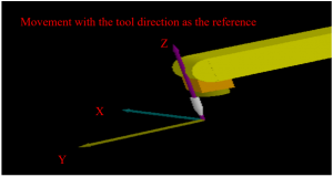
The figure below serves as an example:
2. Tool calibration
Purposes of tool calibration
The sizes of all parts of robot are determined at design stage, and the coordinates of origins of all joints can be completed via origin calibration. However, when tools are installed onto the robot arm, the installation error or different working point could result in inconsistency between thepreset tool parameters and actual installation situation, and the function of “Tool calibration” is for correction of such “compensation value.” The calculations during point calibration or path operation are all based on tool endpoint.
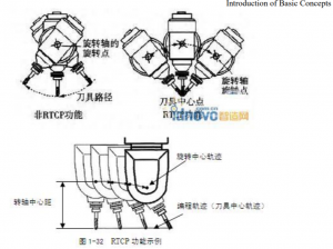
Therefore, the provision of correct dimension of mechanism part is the most fundamental requirement during calculation. The function of RTCP (Rotational Tool Center Point) can only be achieved with correct dimension of mechanism. The functions of RTCP are described in the following section by figures retrieved from the Internet.
Classification of tool calibration
There are three kinds of parameters of tool installation, which can be divided into two categories:
1. Offset direction and offset distance
2. Tool length
Depending on the type of mechanism, calibration functions don’t necessary contain all items, and they are mainly determined in accordance with the degree of freedom, such as:
Six-joint: 1 Offset direction and offset distance and 2 tool length
Scara:1 Offset direction and offset distance
Delta:1 Offset direction and offset distance
XYZABC:1 Offset direction and offset distance and 2 tool length
3. Various coordinates and their correlation
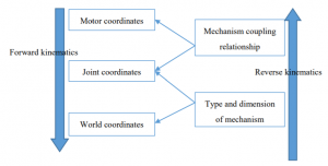
There are numerous types of robots. For convenience, the position of motor rotation must be converted into the world coordinates presentation of tool endpoint via the algorithms specialized for the type and dimension of mechanism. Several specific terms involved are as described below Motor coordinates: The actual coordinates of motor is not related to the common actions among mechanisms. Joint coordinates: The coordinates converted from motor coordinates via a mechanism coupling relationship. (Visible mechanism status) World coordinates: The position and stance of tool endpoint with the center of robot base as the origin. Forward kinematics: The algorithm of transform from motor coordinates to world coordinates. Reverse kinematics: The algorithm of transform from world coordinates to motor coordinates.
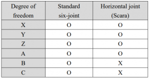
Degree of freedom: The expression of spatial coordinates including six elements of XYZABC. A certain number of elements could be missing when there is insufficient number of robot axes or difference in design method. Take two types of robots as the examples, and degrees of freedom are as shown below:
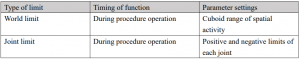
The restriction of movement range of robot must be achieved by limit setting. The limits of articulated robot can be divided into two categories:
4. Introduction of various coordinates
In addition to the aforementioned motor coordinates, joint coordinates, and world coordinates, normal coordinate systems not related to the type of mechanism will also be used to facilitate point calibration, generic nature of procedures, and procedure porting in order to express the position and stance of tool endpoint. The coordinate systems a further explained in this manual.
4.1. World coordinates
It is the coordinate expression method with the origin and direction defined by the mechanism as the origin, and the XYZ directional axes of Cartesian coordinate as the standard. For every type
of mechanism, the meaning of world coordinates is the distance (X, Y, Z) and direction (A, B, C) of tool endpoint from the origin of mechanism. When being used in the procedure, the scenarios suitable for the use of world coordinates are as
shown below:
1. Not related to the position of machining: For example, when a robot arm is moving objects between two work zones, there will be a waiting position between these two work zones, and the world coordinates can be used for this position.
2. The machining procedure provided for small-volume production: If there is only one machine available in the factor for single machining, the procedure will not be ported to another robot for machining. So the world coordinates can be directly used as the procedure operation coordinate system to save the marking process between robot and work piece.
4.2. Work coordinates
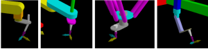
When the robot is used for adhesive coating and polishing, all actions are determined by the positions of workpieces. When multiple machines conduct identical work in the production line,every machine must use an identical machining procedure. However, it is difficult for the relative positions between machine and workpiece to be consistent with each other, thus the coordinate system must be defined to describe the position and rotational angle of workpiece. The editing of procedure is better to be in accordance with one specific work coordinate system, such that during the modification of reference position of subsequent action, the procedure transfer can be completed by simply changing the definition of work coordinate system without the need for re-modifying the relevant action points. As shown in the figure below, that two sets of workpieces are identical, and they are just placed at different positions and angles. Therefore, the path can be edited by work coordinate systemapproach with respect to normally placed workpiece during the procedure editing. When another workpiece is to be machined, it can be done by switching the work coordinate system to the reference position of that particular set of workpiece.
4.3. Tool coordinates
During procedure operation process, sometimes there must be movement along the direction of the tip of robot, such as the material accessing and replacing actions of lathe, in which the workpiece must be taken out or placed in a straight line along the direction of tip of robot. It is called tool coordinate system because there will be another tool installed at the tip of robot. When there is the need for taking action with the current stance as the reference during the procedure, it can be set to use the tool coordinate system.
4.4. Joint coordinates
The joint coordinates are based on the joint angle as the basis for movement, which is not related to the dimension of mechanism. The joint movement will not involve any problem of singular point during calculation, such that it is usually used for cases crossing singular points. Attention must be paid to the collision issue during the use of this coordinate system.
4.5. Motor coordinates
It is the most original motor position after exclusion of coupling relationship of joint. The movement under maintenance mode is based on the motor coordinates, and it is usually used for origin calibration
Demonstration movement
The demonstration operation section is as shown below, which can be used for the robot
operations based on various coordinates.
Under “Maintenance mode”: The operation is implemented with respect to a single motor
coordinate without taking into consideration the impact of mechanism coupling.
Under “Automatic mode”: If operations are switched to the hand wheel mode, x1, x10, and x100
can be selected.
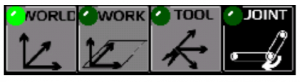
Under “Demonstration mode”: There are four kinds of coordinate that can be selected, such as
world, work, tool, and joint.
Before coordinate adjustment, operation must be switched to the “Demonstration mode” in order
to activate the adjustment procedure
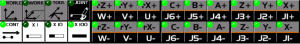
Continuous/incremental
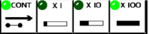
The movement method can be switched between continuous and incremental by pressing the continuous key. Pressing 18 keys under “Continuous” will allow the adjusted action to move in accordance with the selected function until the keys are released. The speed of movement can be determined by the three speed selection keys below. Pressing 18 keys under “Incremental” will allow the robot to move by a certain distance, which will be determined by the three distance selection keys below. The usual approach is: When the distance is far enough from the target point, the use of “Continuous” will allow it to approach the target point sooner; when it is getting close to the target position, it should be switched to “Incremental” approach to reach the target point more precisely.
The coordinate system as the reference for movement
The movement direction should be converted in accordance with the selected coordinate system. Precautions: If the system is in the state of “Not ready”, the “Demonstration” can only be based on “Joint coordinates”.
– World coordinate system: It is fixed. The axial direction of coordinate system as the reference during adjustment should be determined in accordance with the definition of world coordinates.
– Work coordinate system: The axial direction of coordinate system as the reference during adjustment should be determined in accordance with the set value of work coordinate system.
– Tool coordinate system: The axial direction of coordinate system as the reference during adjustment should be determined in accordance with the set value of tool coordinate system. “Tool” can be pressed to set the position and stance of current endpoint as the current tool coordinate system, and the values nearby will also become 0, which indicates the spatial distance between the position of endpoint after movement and the position of endpoint at the moment of pressing “Tool”. Joint coordinate system: It is fixed in accordance with the definition of joint coordinates.
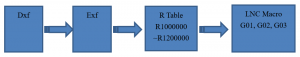
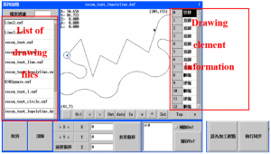
Drawing file processing
This system is capable of analyzing 2D Dxf drawing file by converting it into the drawing element information file (Exf) for the system before the element information can be written into R1000000~R1200000. Users can read the drawing element information from this R value section via LNC Macro Language, and then it can be converted into the actual processing coordinates in accordance with actual processing needs before being converted into a movement command. This process flow is based on the principle as shown below:
| Can set up to 5 levels of privileges |
|
| Movement | – MPG / JOG / MDI
|
| Teaching Mode |
|
| File Support |
|
| Other |
|


Rtcp, work plan, robots CNC control. Point stop the rest move
LNC robot controller teaching mode
Lnc controller move x y z a b axis manual
Lnc robot controller change to English


 salecnc.com
 salecnc.com
Reviews
There are no reviews yet.